Device Description
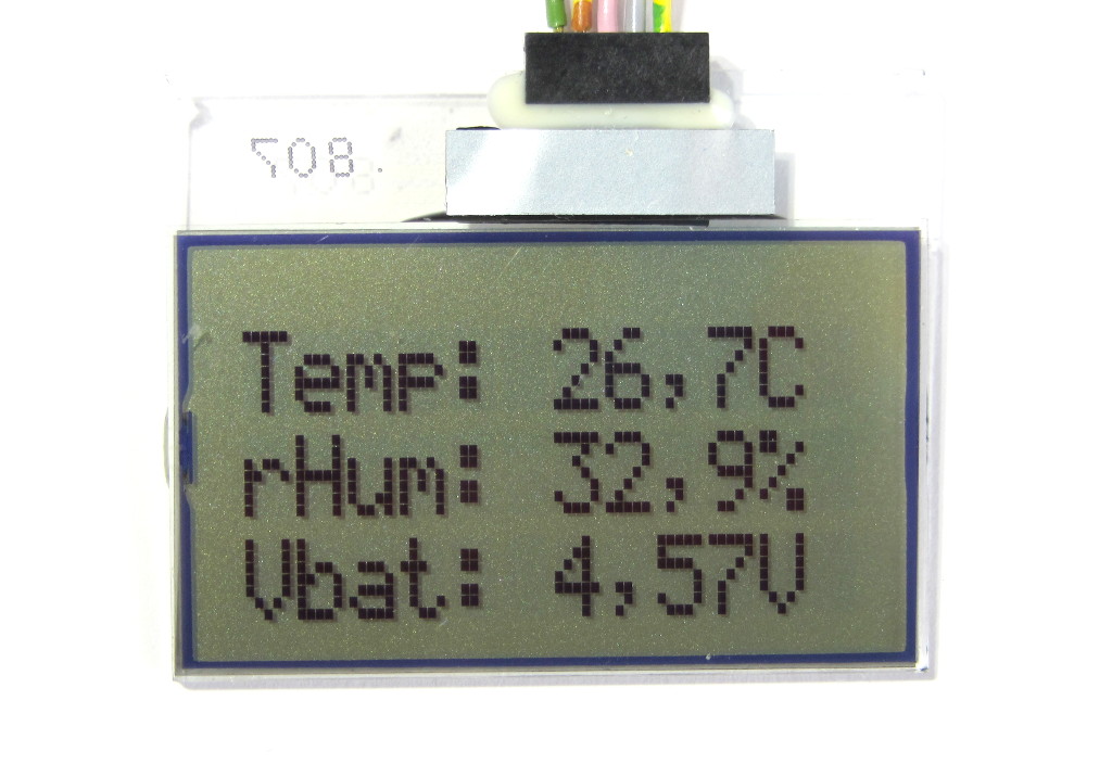
This article is about a little homemade device that shows humidity, temperature and supply voltage on a little LCD display. The main “feature” of this homebrew project is it’s very low power consumption, which is in average 150µA at 3.6Volts. This allows the device to operate on three AAA batteries for well over one year.
Motivation for the project
If you want to have a humidity indicator for your apartment, it is probably much easier to simply buy one. They are sold for very decent prices and if you pick the right one, the precision is rather acceptable. It is probably fair to say that measuring humidity very precisely is really difficult. So whatever you get for home usage, is likely in the precision range of +-3% or worse.
The reason why I did this project, was to see how much functionally can be squeezed into the 1024 Bytes of flash memory, that the ATtiny13A offers. Using almost all of the hardware features in the ATtiny13A, it was really amazing how much functionally did fit into this little work horse. Also the low pin count, of 8 pins in total, did create a challenge for the circuit design, which I was happy to accept.
Hardware Design
The circuit is basically made of three main components:
- Micro-controller ATMEL AVR ATtiny13A, programmed in C using the avr-gcc compiler
- Humidity and temperatures sensor AM2302, with proprietary pulse length interface
- An old mobile phone LCD with I2C interface (taken from an Ericsson SH888)
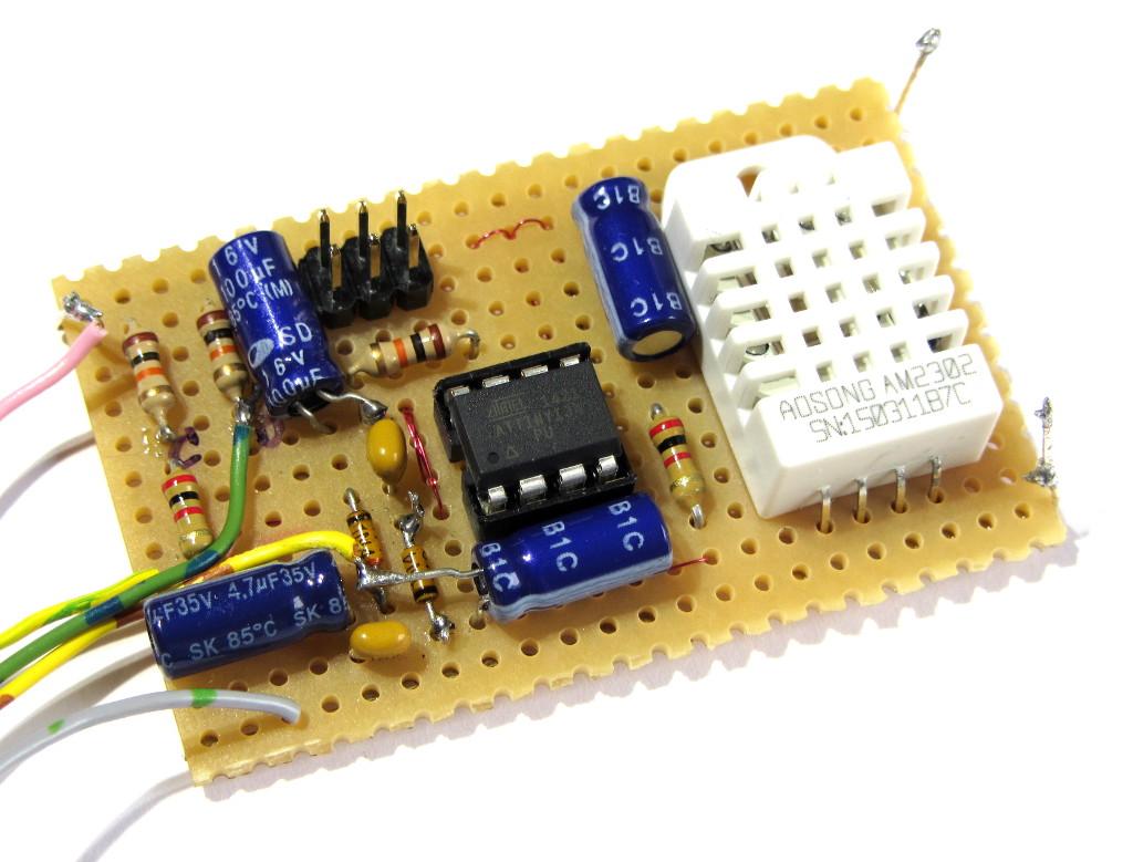
I have build the circuit on a small piece of prototype board. And since the project was mostly for fun, I do not intend to ever do a printed circuit board.
Schematic Diagram
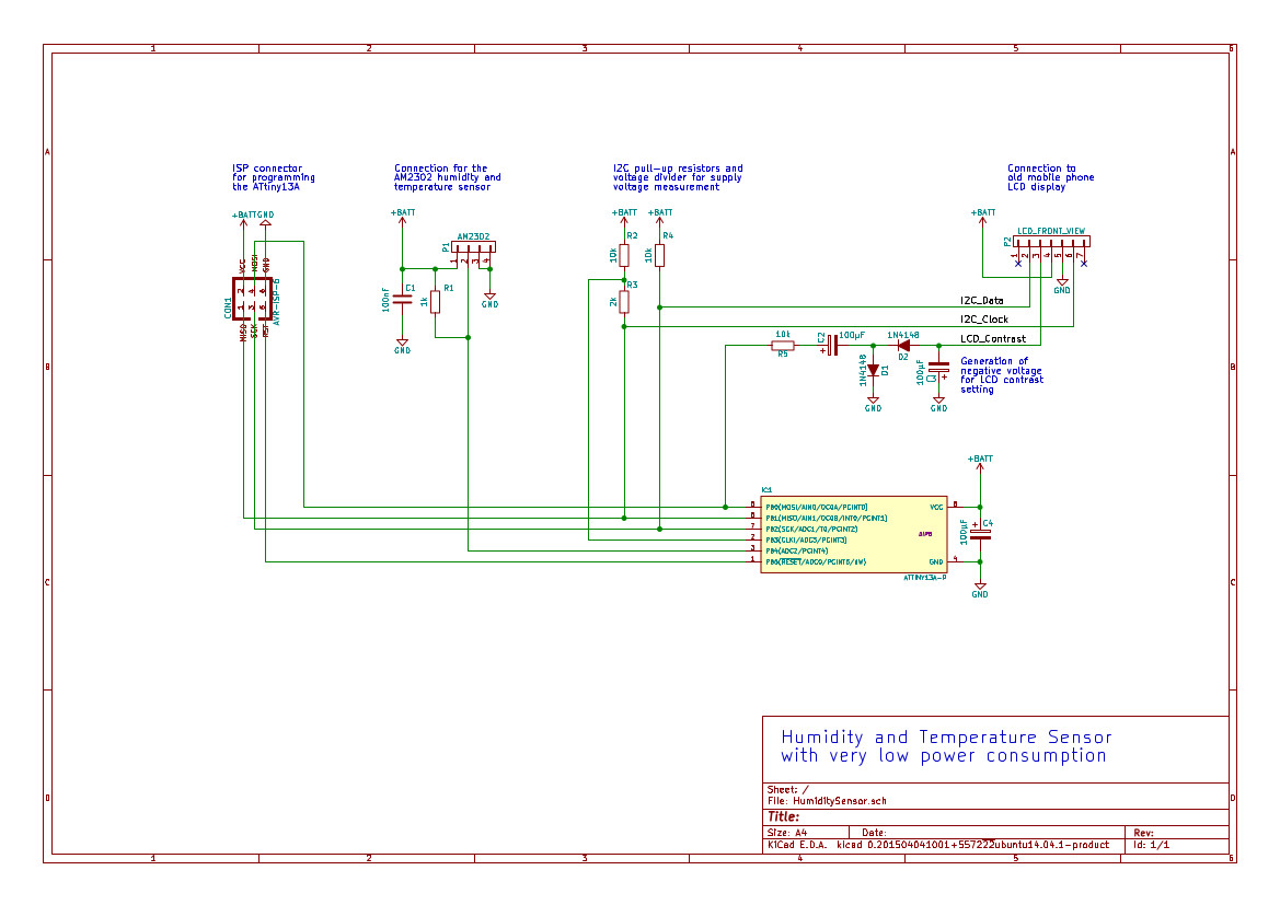
The schematic is in fact rather simple. The LCD and the humidity sensor are basically directly connected to the micro-controller. The only tricky part was the generation of the negative voltage that is needed by the display, to control the contrast. Since this contrast voltage needs to be adjusted when the supply voltage changes (i.e. when the batteries slowly run out), I needed a way to control this negative voltage by software. And of course I needed a circuit that does not kill all my efforts to save as much power as possible. Another challenge was to convert the battery voltage to a voltage level that can be measured against the internal band gap voltage reference in the ATtiny13A, without adding a resistive voltage divider that uses up battery power all the time. I have solved this problem by splitting one of the I2C pull-up resistors into a voltage divider. That allows me to switch on the voltage divider when I need it, without the need for another GPIO pin on the ATtiny13A, which I actually did not have any more.
Click on the picture below to get a high quality schematic in .pdf format.
Software for the micro-controller
As said, my goal was to squeeze as many features into the available 1024 Bytes of flash memory. And I did not stop before I had used up 1018 Bytes, which means I have only 6 Bytes left for any updates.
The following is a list of all the functionality that is part of the software.
- Read out the internal ADC of the ATtiny13A to measure the battery voltage
- Read the external humidity and temperature sensor via the proprietary pulse width interface
- Calculate the checksum of the data from the sensor and compare it to the received data
- Implement a software I2C interface for the LCD
- Send the control and data information to the LCD via the I2C interface
- Convert the measurement results into single decimal digits to show them on the LCD
- Generate pulses of adjustable high/low ratio, to adjust the contrast voltage
- Determine the best contrast value as a function of the battery voltage
- Go into sleep mode for 30 seconds in between the sensor readings, to save power, with sleep mode interruptions every 250ms, to generate contrast pulses for the LCD
Most of these features I have implemented straight forward in C, without spending too much special efforts to save flash memory. The only thing that I had to do in a rather manual way was the conversion of the measurement results into decimal digits. I have tried to simply use the sprintf instruction, but that eats up way to much memory. So have done the calculations digit by digit.
The software is available under the GNU GPL 3 license in source and as compiled binary for the ATtiny13. You find both conveniently packed into a .zip file below.
Measurement results
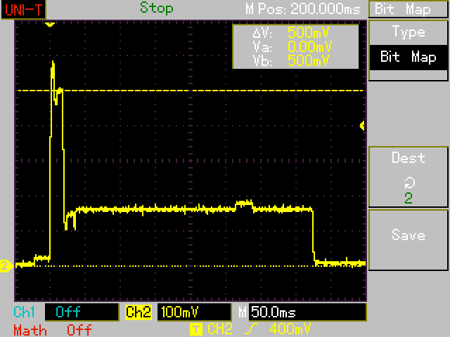
Measuring the current consumption of the circuit is not trivial, as it changes a lot over time. In active mode, the circuit draws about 5mA. That phase is very short, as the ATtiny13A is put into sleep mode immediately after the sensor readings. Unfortunately the AM2302 sensor takes a little while to go into sleep mode as well, during that time it still consumes some relevant power. Then, during sleep mode, the current consumption is below 100µA, the short pulses for the LCD do not contribute to the overall power consumption significantly.
The picture shows the active phase of 5mA (measured as voltage on a 100Ohm shunt resistor) for about 20ms. After that, the ATtiny13A is being put into sleep. Then the rather long phase (about 375ms) can be seen, when the sensor is still in active mode. During this time a little increase for about 20ms, about 0,3mA high is visible. that is when the ATtiny13A wakes up in down-clocked mode (37.5kHz) and outputs the pulse for the LCD contrast generation. The remaining current usage during the sleep mode phase of all components is very hard to see in the picture, as it is below 100µA. This phase takes about 30 seconds, which pushes down the average power consumption a lot.
Precision of the sensor readings
The precision of the AM2302 is not perfect, as all consumer grade humidity sensors are. But I had ordered three pieces and picked the one that gave me the best fitting readings compared to some lab grade analogue humidity and temperature meters. Assuming my reference meters are correct, I am now in the range of +-1% for the humidity and +-0.2°C for the temperature.


